
Sailing Test Platform - So Close!

With the autonomous navigation of a boat proven (see previous blog post), it's time to prove we can sail an autonomous boat. We chose a sloop rig boat as it's a practical rig that we all understand (see future blog posts about wing sailing). Sticking to the philosophy of rapid iteration and easy construction, I designed a monohull boat around a length of 110 mm soil pipe.
Related posts:

Some stats:
length 2.4m exactly
Beam 110mm
Draft 500mm
Hight of the rig 1100 mm
Sail area 1 sqm
Actuator 800mm travel home brew linear actuator
Keel mass 6 kg
Displacement 11kg
The boat has a completely round cross-section so has absolutely zero form stability. The boat stays the right way up by having its centre of gravity a long way below the water line. This gives it qualities much like a weeble, it heels quite readily as the righting force grows with the Sin of the heel angle. It does have the major advantage of (much like a weeble ) only having one stable orientation - the right way up. This a very useful quality for an autonomous boat as it's completely impossible to capsize, unlike say a catamaran, which could be capsized and have no means of self-righting.

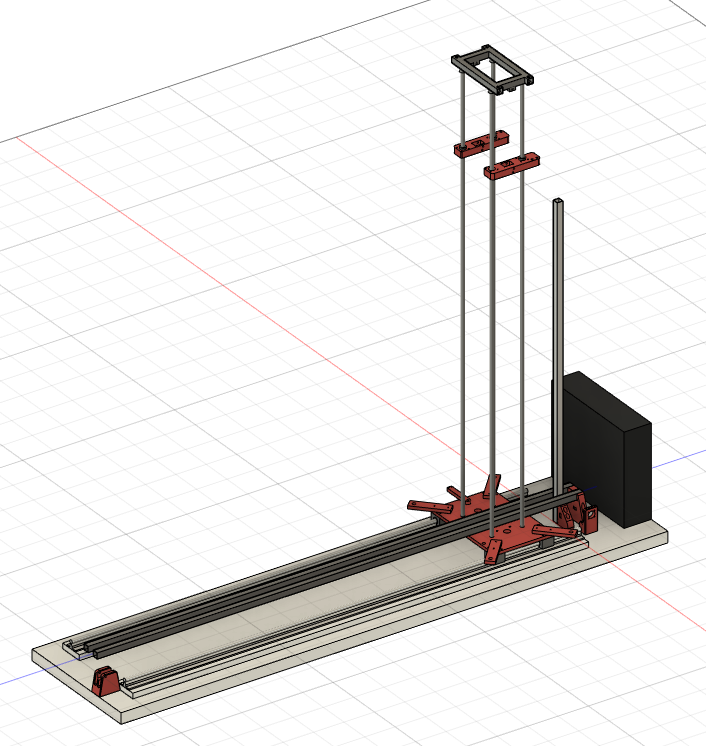
So with a plan in hand, it was time to print a bunch of bits.
Primarily the mast partner print and two nose cones.

All the force from the keel is transmitted to the mast via this huge printed part called the mast partner that slips inside the tube and is epoxied in place. A length of PVC bar running athwartship about 118mm long goes through the mast partner and through two holes in the tube. The bar helps distribute the force into the tube and the mast partner and keeps the force from the nuts on the threaded rod securing the keel plates from squashing the tube.

The mast partner also contains the hole for the stub mast (a short length of aluminium bar that the mast fits onto). The stub mast and athwartship PVC bar are all epoxyed to the hull tube.
The nose cones are large printed parts glued to the ends of the tube and have integrated holes for the backstay and cord sewed into the leach of the jib. The forward nose cone is a wave piercing design (as it was amusing) and the aft nose cone is vaguely more traditional shape (for a boat made of drain pipe haha).

The keel is another blog post altogether, given its numerous iterations and complexity
Link to so close actuator project https://robotboatpioneers.blogspot.com/2023/01/makeing-keel-of-so-close.html
The sails are made of rip-stop Nylon and are just flat triangles (don't worry, they do work and it does go upwind). All the edges have 550 paracord sewn into them. They are different colours to help identify which way round the boat is at a great distance.
I made the sails at my local Maker Space. Pictured in the Swindon maker space

The hull was first filled with expanded polystyrene disks cut on the CNC hot wire. I'm not the kind of chap that builds boats that can sink. The rest of the bits were glued on with plenty of epoxy. There are three athwartship PVC rods. The forward one and centre are to secure the keel plates to. The aft one was never used, but was for later expansion if the boat needed extra bits bolted on.
There's a tube through the hull that the rudder runs through. Keeping the holes in the hull minimal and glueing them up with plenty of epoxy was very successful as the last hole through the hull was a plumbing fitting which can be taken off to inspect the inside for water ingress. It also allowed us to pressure test (with a bike pump) the hull for leaks.
 |
| Assembly montage |
The rudder is actuated by a standard 20kg-cm servo which was stripped down and completely filled with grease. The grease is for waterproofing, the theory being where the grease is the water isn't. It's a messy job, but I'm confident the circuit board, motor and gears are all safely protected. It does draw a bit more current though as all the grease has to be pushed out of the way of all the gears. So far all the grease packed servos have been bulletproof and we haven't had a failure, even when they get fully submerged in the lake.
The sails are operated by a linear actuator with a travel of 800mm. Both sails are operated by the same actuator, which is less than ideal but as the actuator is huge, there’s not enough room on the hull to have two. The actuator uses a servo signal to know where to go, so the entire boat can be operated by a two channel RC radio which was useful for testing before we had assembled all the brains (where brain = microcontroller).
The details of the actuator are in this blog post: Link to So Close actuator project
The boat was optimised to be rigged easily at the side of the lake and fit into an estate car without issue. The boat was assembled by the lakeside and lifted into the water. She performs quite well going upwind and downwind. The sail plan is a bit limiting with the actuator being connected to both sails. The rig is also somewhat limited by the spar in the foot of the jib, its a compromise, but it lets the rig be self-tacking as the eye of the jib sheet is just forward of the mast instead of almost all the way aft to give the jib a better shape.
Once proven the boat sailed under RC control it was time to make a control system for it. The control for So Close is another DroneLink motherboard with an ESP32 and supporting parts including compass, GPS, 915mhz radio and the secret software sauce (not very secret, all 140,000 lines are on Github) - the very powerful written-from-scratch software that runs the boat. It knows where the boat is, which way it's pointing, which way the wind is blowing and where it wants to go next. Using this information it plans its course and sets the sails.
The control system is a spectacularly complex and powerful bit of software that can turn its hand to any RC vehicle, so that can be another complementary blog post.
Link to So Close brains project

So Close (as it got named on the lakeside) performed well under autonomous control in a series of tests and helped us improve the sailing algorithms drastically. This was an excellent step towards our ultimate goal of the Microtransat challenge, but the plan for the boat for the crossing will have a wing sail as it's more robust and practical.
But that's a series of blog posts for the future.


Comments
Post a Comment