
First Test Boats - Paddle 1, 2 and 3
After talking about making autonomous boats for a number of years and finally having all the skills together at the same time, we needed a test boat to program and drive about. Much like Space X, rapid iterations were the best path. For us, that's lots of hot glue and cable ties.
The goal was to keep the test boat as simple, fast, and cheap as possible to build, so we settled on a paddle boat design with an independent drive to each paddle so it would drive like a tank.
Original concept

Version 1
I threw together a few circles on CAD and sliced them out of a sheet of expanded polystyrene (see CNC Hot-Wire post for details).

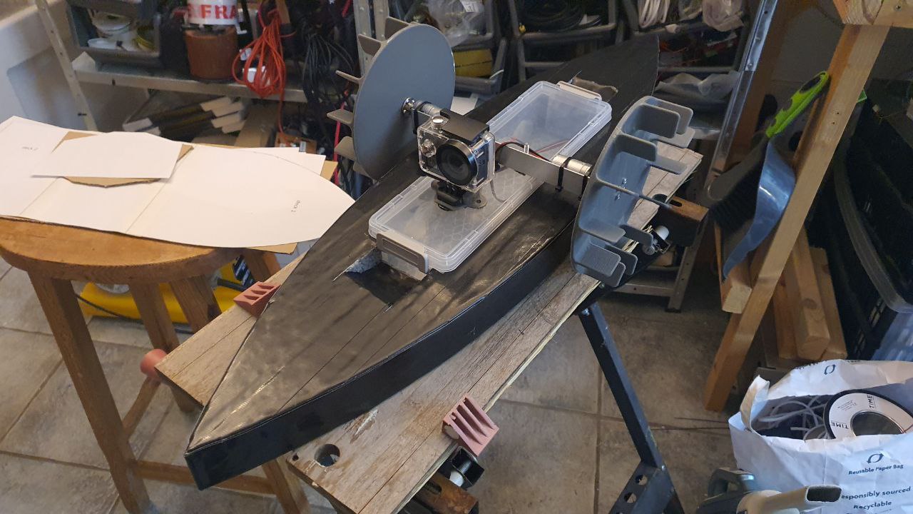
Having cut the hull out of foam, we glued a lunch box to it to hold the electronics, then bolted a length of aluminum right-angle to it to hold the motors/paddles. The paddle wheels were 3D printed and bolted to the motor shafts with little shaft adapters.

For the electronics, we made a custom PCB with an ESP32, I2C multiplexer, 5v, and 3v3 power regulators, and a dual H-Bridge driver to control the motors.

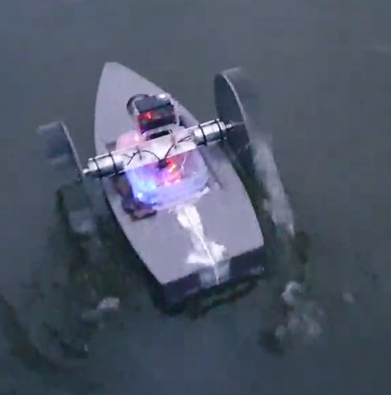
We found a nice lake and threw it in. It performed well under manual control and with that, we definitely had a platform to test software and sensors on. The next stages were to add additional sensors like a compass and GPS to enable automated waypoint missions.
Version 2
Turns out the glue we used for version 1 was not at all waterproof and while the hull shape looks like a boat, the flat back created a lot of unnecessary drag. The next design was pointy at both ends and used polyurethane glue. It also got a longer slimmer waterproof box and a slimmer overall profile to help it go faster. To toughen up the polystyrene hull, it received a coat of black gaffer tape which made it much stronger.
The electronics were extended with a GPS module, a 9-DOF IMU (3-axis gyroscope, 3-axis accelerometer, and 3-axis compass) module and a 915mhz radio for communication. The software was also significantly extended to leverage the extra sensor data and perform waypoint missions.
See DroneLink System - Boat Brains article for an overview.

 |
| Second boat under construction |
The second boat finished
Version 3
Although the gaffer tape made the hull stronger, the water creeps between the tape and the foam and spends days dripping back out again. The lid of the electronics box only loosely clipped on, with no gaskets or seals to keep the water out which turned out to be a great problem as the paddle wheels flick water everywhere.

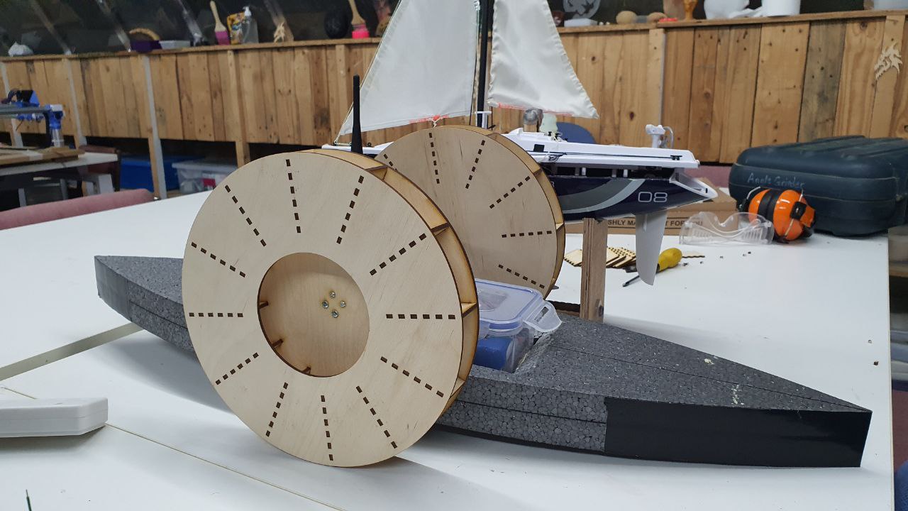
The version 3 boat has a water-tight box with a gasket and clips all the way around and improved paddle wheels. The printed ones were OK, but water could flow out sideways around the end of each fin losing efficiency, whereas the new wheels have a wall on the outside to constrain the flow of water. The new wheels were also laser cut from plywood at our local Makerspace and varnished for waterproofness.

The boat is now a reliable little workhorse, used for a mix of retrieving other stuck boats and occasionally as a radio relay for other tests, which I will write about in a future post.


Comments
Post a Comment