
DroneLink Architecture - "Boat Brains"
From the moment we started discussing the Microtransat project, it was clear we would need a fairly sophisticated software/electronics stack to support the development process - what has evolved into our DroneLink platform. Our initial requirements were for it to be flexible/extensible, support a fleet of test boats (traditional sail, wing sail or motorised) and help us monitor/learn as we went along. It should also be easy to use by the non-developers on the team (i.e. the Joshes).
A couple of years on and DroneLink has evolved into a competent platform for building not just autonomous boats, but a variety of autonomous devices - it underpins and manages our fleet of test boats, base stations, trackers and anything else we've needed as the project progresses.
The diagram below illustrates the main components, explained in more detail below:

Boat (Drone) Control
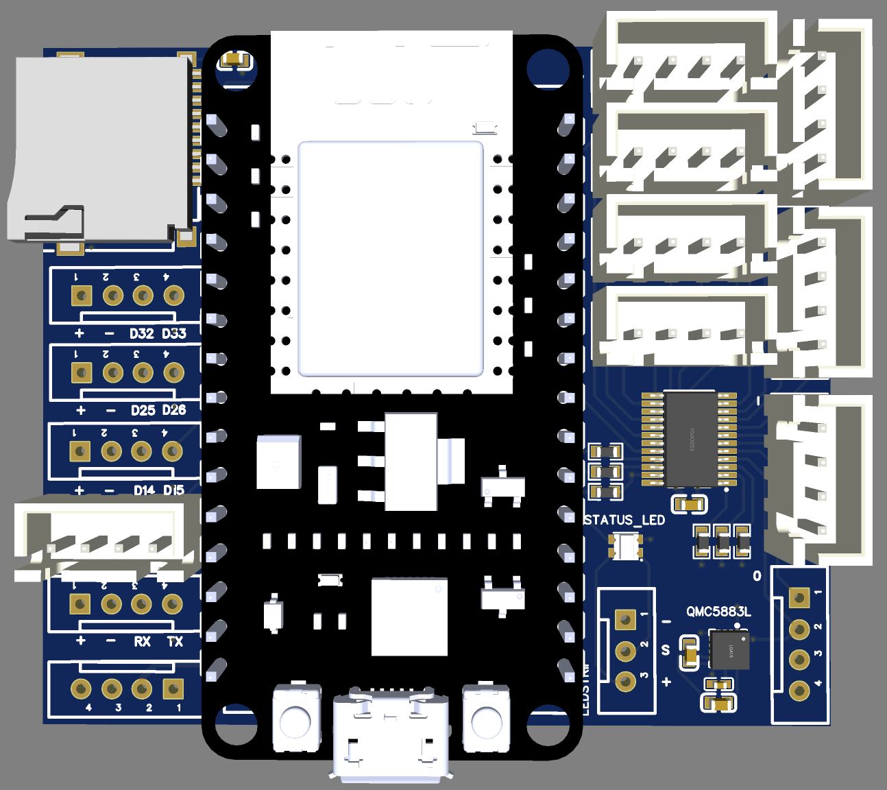
Each boat (or other device) is based on a custom ESP32-based motherboard running our DroneNode firmware. The firmware exposes a number of sensors, actuators, telemetry interfaces and control modules that can be configured for any given boat (device) through a simple config file. To keep software modules loosely coupled, they communicate using a pub/sub topic model.
Topic addressing is a 3-byte value of the form: < device ID > < module ID > < parameter ID >
Parameters can be up to 16-bytes in length using one of 4 basic data types: 1-byte or 4-byte unsigned int, float, characters string.
The motherboard exposes the ESP32 IO interfaces (digital/analog IO, serial, SPI) and includes an 8-channel I2C expander to make connecting peripheral devices extremely easy. It also includes an onboard GPS, RFM69 radio, QMC5883L compass, status Neopixel and SD card.
The motherboard is complemented by a custom Power Module, that supplies regulated 5V for onboard sensors and includes an INA3221 power sensor for monitoring battery voltage/current levels.
See DroneLink Motherboards - Evolution from v1 to v5 for more details.

Mesh Network
DroneLink devices communicate over a multi-transport mesh network that I developed, named DroneMesh (obviously). It's a fault-tolerant network where any device can act as a router and will bridge multiple transports, selecting the most reliable/fastest connection for each link if multiple are available. Packets are tagged with priority levels to help manage link congestion and support either reliable or fire-and-forget delivery.
So far I've implemented transport interfaces for:
- UDP over WiFi
- RFM69-based short-range packet radio on 915Mhz or 433Mhz
- Point to point using 433Mhz telemetry modules
- Point to point over serial (for local hard-wired connections)
Central Management
For monitoring and control, we have a NodeJS-based server instance that manages the DroneMesh connections from a host computer (Windows, Mac, etc) and hosts a web-based management UI. The Web UI has become quite sophisticated and supports a bunch of features to make our lives easier:
- Manage multiple devices in parallel - with a custom UI dynamically created for each device; local filesystem access; custom visualisations and configuration node-view
- Map view with overlays to show GPS locations of devices, compass heading, local wind direction
- Network topology view to visualise and debug DroneMesh status
- Packet histogram view to analyse over-air traffic, data rates and packet prioritisation
- Logging to and playback from cloud storage (FireBase) to enable offline analysis


Future posts will explore all of the elements mentioned above in more detail.


Comments
Post a Comment